Aharonov-Bohm_effect.svg

Size of this PNG preview of this SVG file:
426 × 166 pixels
.
Other resolutions:
320 × 125 pixels
|
640 × 249 pixels
|
1,024 × 399 pixels
|
1,280 × 499 pixels
|
2,560 × 998 pixels
.
Summary
| Description |
English:
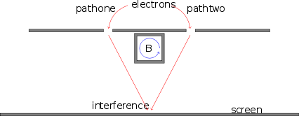
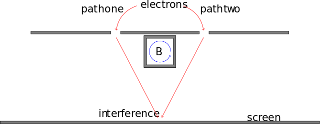
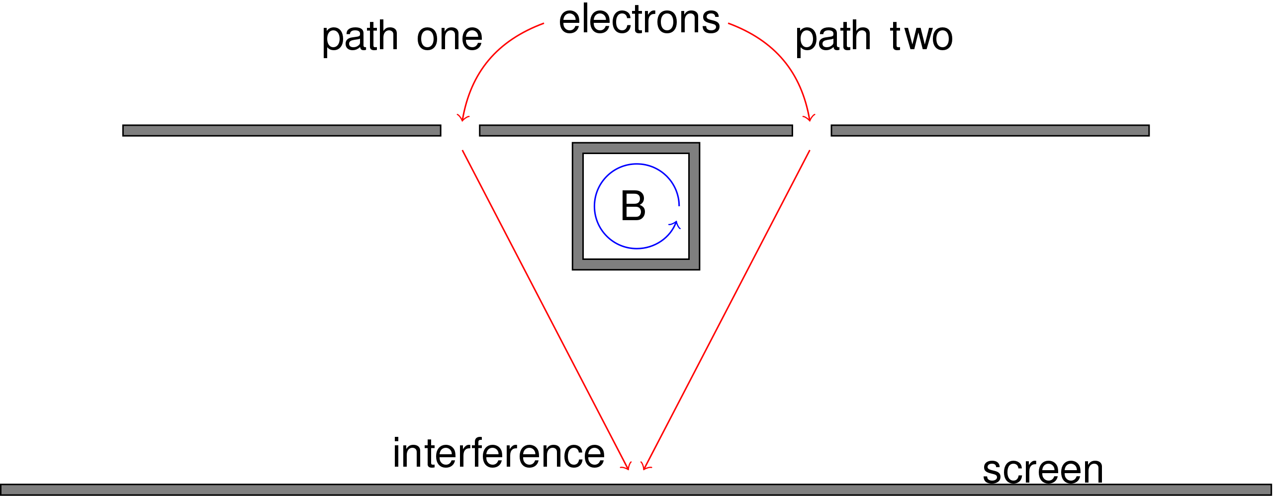
Illustrating the Aharonov-Bohm effect in an interference experiment.
Deutsch:
Darstellung des Aharonov-Bohm Effekts in einem Interferenz-Experiment.
|
| Date | |
| Source | Own work |
| Author | Sebastian Schmittner |
Licensing
I, the copyright holder of this work, hereby publish it under the following license:
This file is licensed under the
Creative Commons
Attribution-Share Alike 3.0 Unported
license.
-
You are free:
- to share – to copy, distribute and transmit the work
- to remix – to adapt the work
-
Under the following conditions:
- attribution – You must give appropriate credit, provide a link to the license, and indicate if changes were made. You may do so in any reasonable manner, but not in any way that suggests the licensor endorses you or your use.
- share alike – If you remix, transform, or build upon the material, you must distribute your contributions under the same or compatible license as the original.
LaTeX (TikZ) source code for this Image
   \begin{tikzpicture}
   \pgfmathsetlengthmacro{\scale}{1cm};
   %
   %Layout anchors:
   \node(e) at (0,0){electrons};
   \node[below left=\scale of e](l){};
   \node[below right=\scale of e](r){};
   \pgfmathparse{\scale * 4};
   \node[below = \pgfmathresult pt of e](screen){};
   %
   %B-field:
   \node[draw,fill=gray, minimum width = \scale*1.2, minimum
   height=\scale*1.2, below =\scale*0.9 of e]{};
   \node[draw,fill=white, minimum width = \scale, minimum height=\scale, below =
   \scale of e](B){$B$};
   \pgfmathparse{\scale * 0.4};
   \draw[->,blue] ($(B.east)+(-0.1*\scale,0)$) arc(0:340:\pgfmathresult pt);
   %
   %Double Slid
   \pgfmathsetlengthmacro{\width}{\scale * 3};
   \pgfmathsetlengthmacro{\thick}{\scale * 0.1};
   \draw[black,fill=gray] (l.west) rectangle +(-\width,\thick);
   \draw[black,fill=gray] (r.east) rectangle +(\width,\thick);
   \draw[black,fill=gray] ($(l.east)+(0.1*\scale,0)$) rectangle
   ($(r.west) + (-0.1*\scale,\thick)$);
   %
   %Screen
   \draw[black,fill=gray] ($(screen)+(2*\width,0)$) rectangle +(-4*\width,-\thick);
   \node[right=3*\scale of screen, yshift=\thick]{screen};
   \node[yshift=3*\thick, left= \thick of screen] {interference} ;
   %
   %beams:
   \path[->, red] (e) edge[bend right] node[black,left=0.2cm, near start]{path one} (l)
   edge[bend left] node[right=0.2cm, near start,black]{path two} (r)
   (l) edge (screen)
   (r) edge (screen);
   %
   \end{tikzpicture}